
C: Fuel System
This is a new section and still under construction some of the pages / links may not be fully working yet.
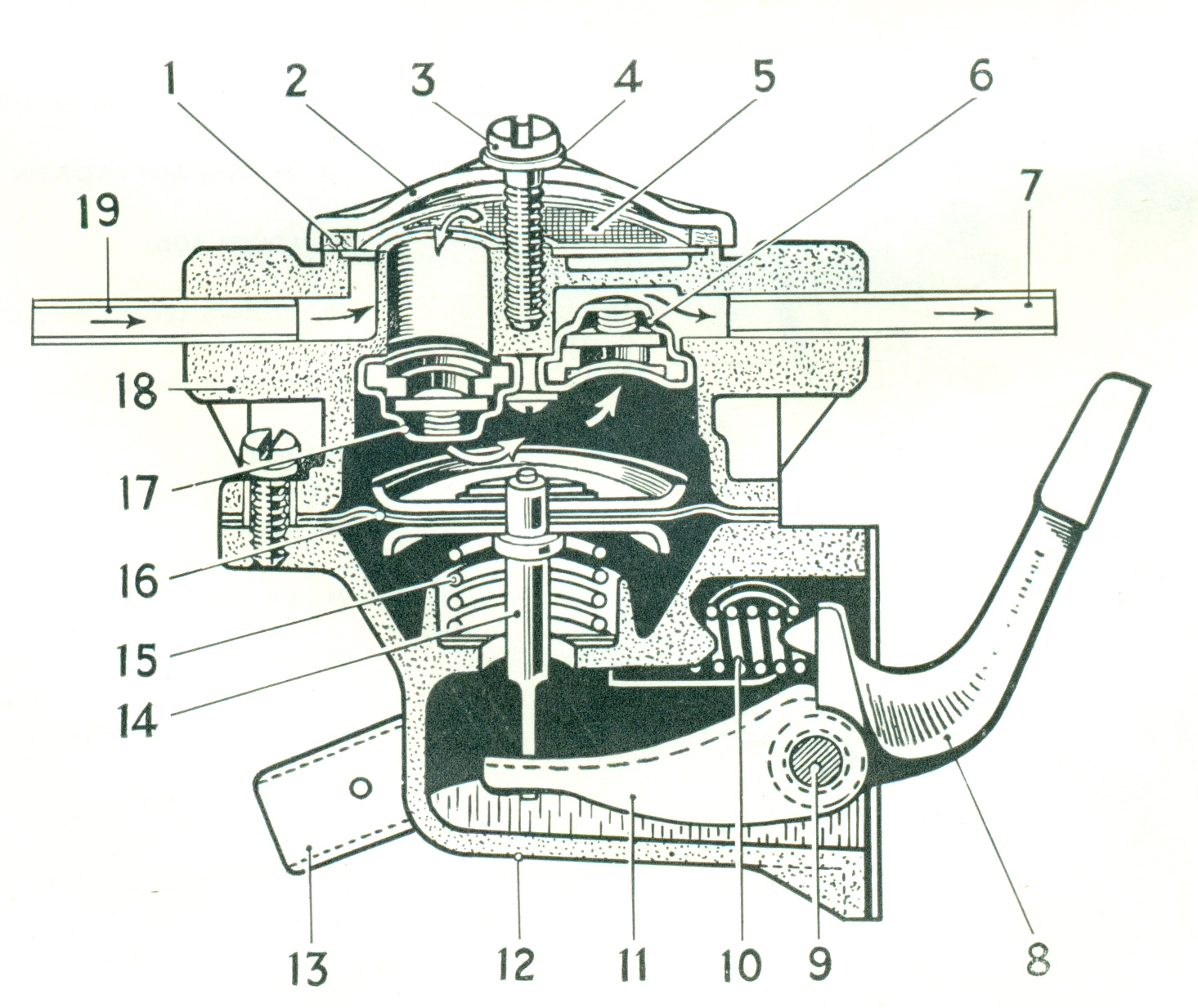
Fuel Pump DESCRIPTION (See Pic) The lower body assembly comprises a rocker arm (8) and link (11), both of which pivot on a pin (9) located in the body. Attached to the link is the pull rod incor porated in the diaphragm assembly (16). To protect the diaphragm from crankcase oil splash, an oil seal is located at the point in the lower body where the push rod passes through. A return spring (15) is interposed between the underside of the diaphragm and the lower body (12). This spring determines the pump output pressure. A further spring (10). is fitted between the rocker arm and the body for the purpose of ensuring that the rocker arm is in constant contact with the eccentric on the camshaft. Also incorporated in the AC fuel lift pump is the hand priming mechanism (13). Assembled in the upper body are two valve assemblies
(6 and 17). one being opened by suction. and the other by
pressure. Both valves are held in position by a common
retaining plate secured inside the upper body by two
screws. |
||
 |
||
 |
 |
|
1 |
2 | 3 |
 |
||
| Man Hours | ||
.
(c) Andy Smith 2025